RACORDER - The Marine Black Box
| Racorder Home Page | Back to Radio Page |
Disassemble the radio:
Remove front panel and shield plate, and unplug the three cables the three cables to the main PCB.
Unplug the two leads going out the rear of the radio.
Remove the five screws which fasten the main PCB.
Remove the two heat sink clips on the sides.
Unsolder the four leads and shield to the PA module.
Unsolder the lead tothe antenna jack.
Unsolder the four power leads in the corner.
Lift out the main PCB and disconnect the ribbon cable to the NMEA PCB.
Remove the NMEA PCB.
Install the Mod Kit:
Carefully drill a hole, .109" (7/64), through the rear of the radio in the dimple between the NMEA hole and the potted leads. Be sure to keep the drill shavings out of the radio.
Pass the output pigtail lead through this hole from the outside.
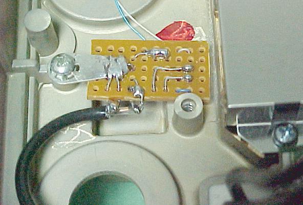
Strip the end of the output pigtail, and solder it to the Mod Kit board as follows: Orient the Mod Kit board so that the components are facing down and the mounting lug toward you. Pass the pigtail shield through the larger hole to the right of the mounting lug and solder it. Solder the inner conductor to the hole labeled "OUT" near where the shield is soldered.
Mount the Mod Kit board to the shallow post at top, with board and components facing down (toward the rear of the radio).
Close-up photo of mounted Mod Kit board
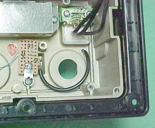
Route the output pigtail around the large hole where the NMEA connector goes so that it will clear wnen the NMEA board is installed.
Photo of mounted Mod Kit board showing routing
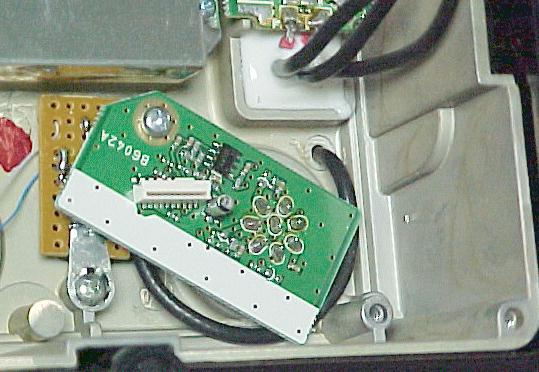
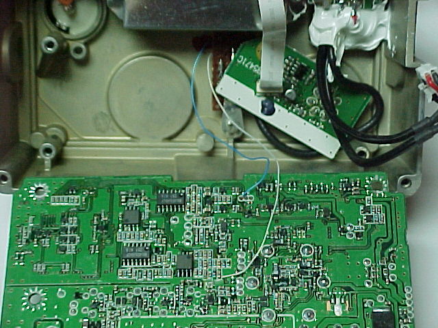
Install the NMEA board; be sure the output pigtail is not pinched or in a bind.
Photo of installation with NMEA board mounted
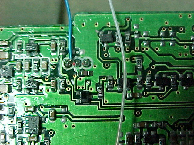
Connect the blue lead from the mod kit board to the receive audio at the volume control connector pin to the left (this has the brown lead from the volume control).
Photo of receive audio connection point
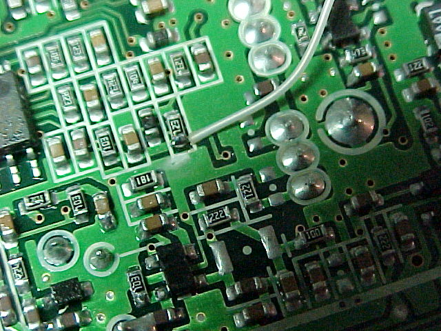
The white lead connects to the transmit audio at the top of the deviation control. We have found two different versions of this model - on the first one the deviation control is R172, later on we came across one where it is R38. In the first instance the white lead can be connected to the 12K (labeled 123) resistor. The other version, connect to the 3300 (labeled 332) resistor.
Photo of transmit audio connection point - radio #1
Photo of transmit audio connection point - radio #2
Photo of completed installation, ready for reassembly
Reassemble the radio:
Reverse the rest of the above disassembly steps.