RACORDER - The Marine Black Box
INSTALLATION OF AUDIO OUTPUT IN THE SEA 156 VHF RADIO
This radio has the squelch gate circuit after the volume control. An ideal installation would require an additional squelch gate circuit in the output line to racorder, available in the mod kit with squelch gate available from Racorder Marine.
Transmit Audio:
Connect a 4.7 megohm resistor (or the white wire from the mod kit) to the junction of R51 (33K) and C60 (22 mf) at the lower left corner of the receive board.
Receive Audio:
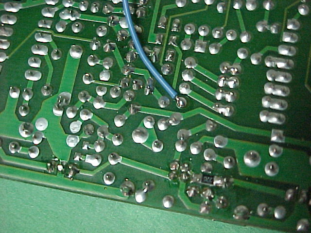
Connect a 1.0 megohm resistor (or the blue wire from the mod kit) to the left end of R24 (1.5K) in the upper center of the receive board.
Squelch Gate Control:
Connect the yellow wire from the mod kit to the left end of CR10 just above TP9 and the transmit audio connection point. The squelch gate control resistor R3 on the mod kit board is 22K ohms.
Squelch Gate Power Connection:
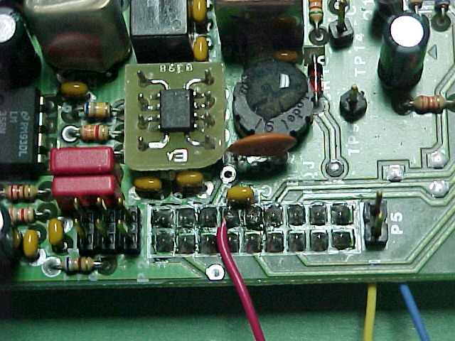
Connect the red wire from the mod kit to pin 15 of connector P2.
PHOTOS:
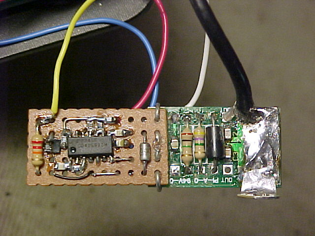
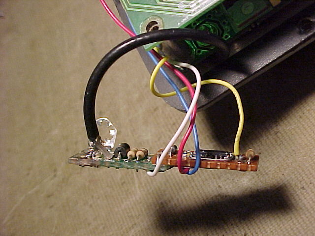
Top view of mod board
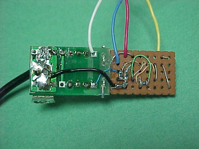
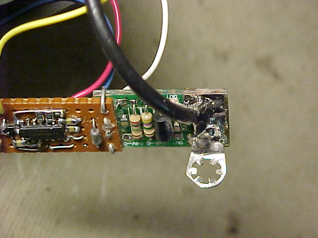
Bottom view of mod board
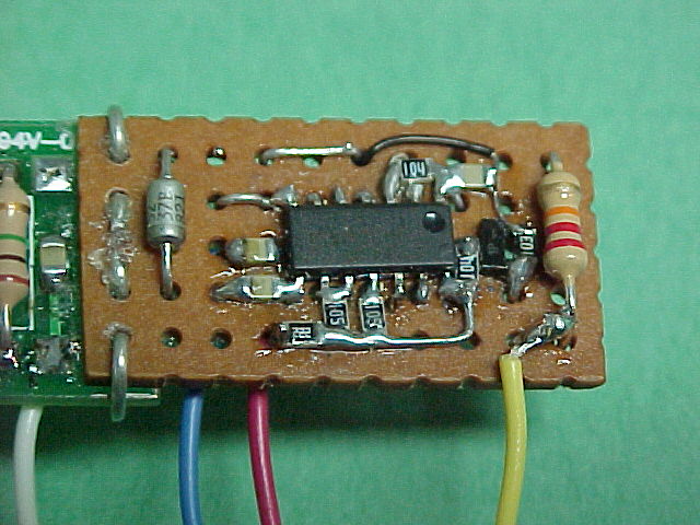
Top view of squelch gate portion of mod board
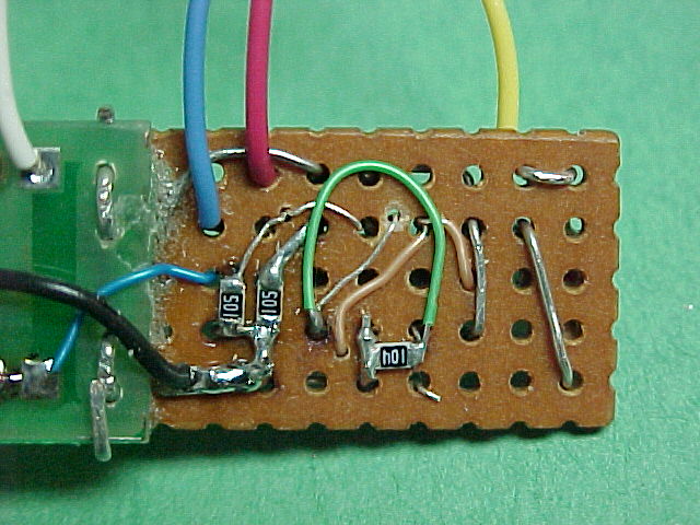
Bottom view of squelch gate portion of mod board
Mod board showing mounting lug orientation
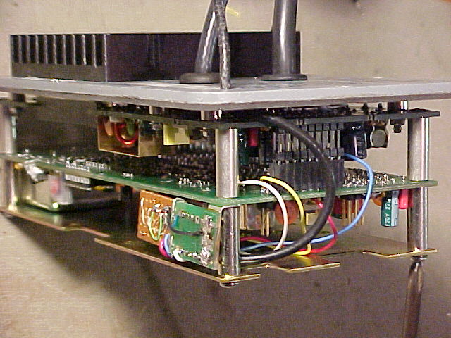
Mounting of mod board
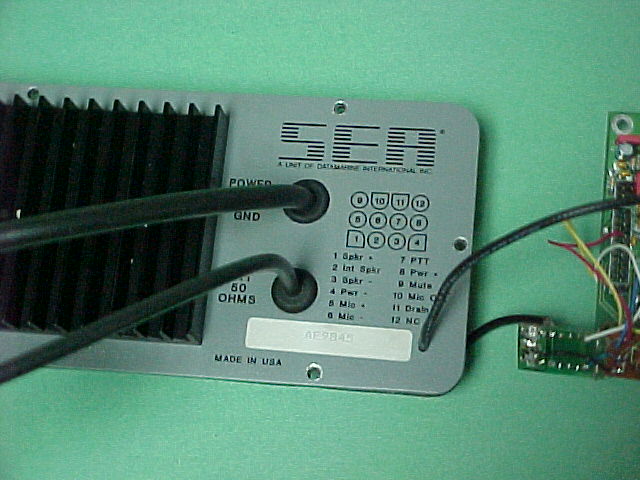
Assembled radio showing mod board
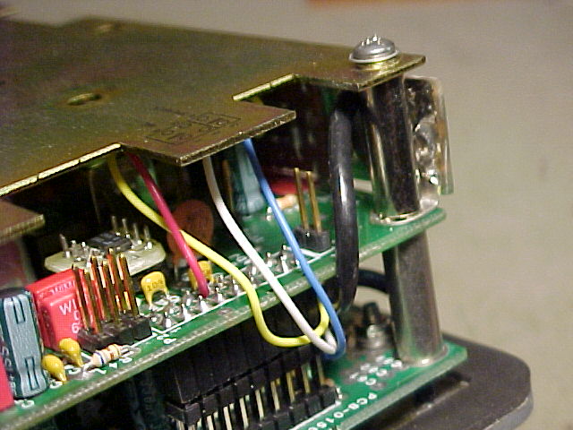
Assembled radio showing wire routing
Rear panel of radio showing cable entry
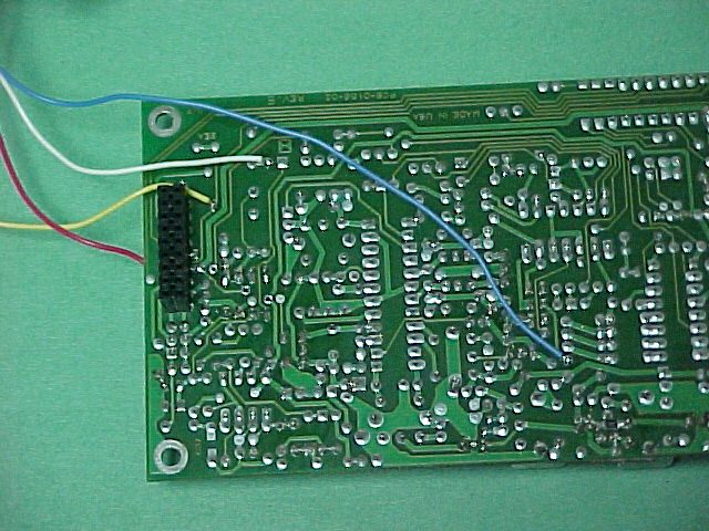
Bottom view of receive board
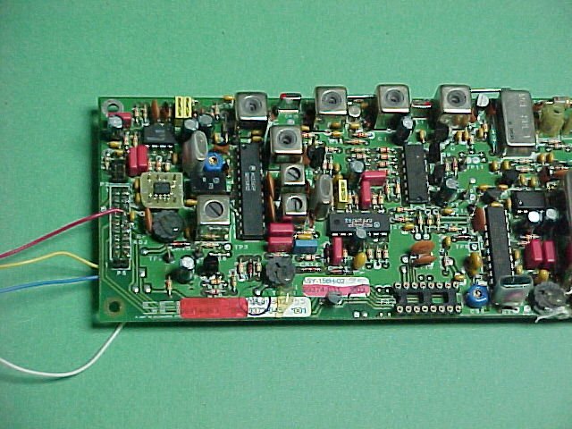
Top view of receive board
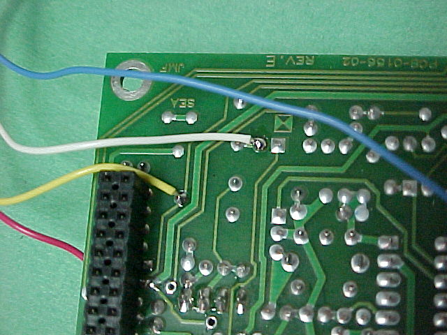
Details of yellow and white wire connections
Details of blue wire connection
Details of red wire connection
Updated July 5, 2004